
Quick Summary: 2D to 3D CAD conversion transforms flat technical drawings into volumetric digital models for modern engineering workflows. Manual methods include extrusion and lofting in software like AutoCAD, ZW3D, and FreeCAD, while emerging AI approaches promise automation for legacy drawing digitization. The process typically takes 30 minutes to several hours depending on complexity, making it essential for manufacturers dealing with legacy parts or supplier drawings that lack 3D data.
Engineers and designers constantly face a familiar challenge: receiving a 2D drawing when what they really need is a 3D model. Sometimes it’s a legacy part from the 1980s that only exists on paper prints. Other times, suppliers provide 2D specifications but withhold complete 3D models to protect proprietary details.
Whatever the reason, the gap between 2D drawings and 3D models creates real bottlenecks in modern manufacturing. Community discussions reveal engineers spending approximately 30 minutes on similar reconstruction exercises—time that could be spent discussing manufacturability and CNC operations.
Here’s the thing though—conversion isn’t always straightforward, and the right approach depends entirely on your starting material, software ecosystem, and accuracy requirements.
Why Convert 2D Drawings to 3D Models?
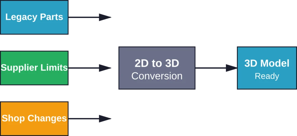
The demand for 3D CAD models in manufacturing continues growing, but legacy systems and supplier limitations mean 2D drawings aren’t disappearing anytime soon. Real talk: this creates specific pain points that conversion addresses directly.
Unavailability of 3D Models from Suppliers
Many websites—including major distributors like McMaster-Carr—offer some components only as 2D prints. For quick proof-of-concept work, requesting 3D models from suppliers is often cumbersome and slow. Engineers frequently mock up placeholder geometry, but that approach lacks precision for fit checks and assembly validation.
Legacy Part Reverse Engineering
Parts engineered before widespread 3D CAD adoption (roughly pre-1980s) exist only as paper drawings or scanned PDFs. When these components need replacement, modification, or integration into modern assemblies, conversion becomes mandatory rather than optional.
Company Cost and Practice Limitations
For manually produced simple parts, some companies determine that 3D models aren’t absolutely necessary. Shop floors can work directly from 2D prints for basic machining operations, so the investment in full 3D modeling never happens—until a downstream partner needs digital geometry.
Proprietary Information Protection
Customers sometimes refuse to hand over complete 3D models to suppliers because they contain internal features and proprietary information. While companies can suppress internal features, many aren’t willing to go the extra mile. Even when they are, it often takes days or weeks to receive the modified CAD file.
Uncontrolled Shop Floor Modifications
Parts undergo modifications during production that get captured only as hand markings on 2D prints. These field changes rarely make it back into CAD systems, creating version control nightmares. Converting the marked-up drawing to 3D preserves these critical modifications in digital form.
Methods for Converting 2D Drawings to 3D Models
Conversion approaches fall into three broad categories: manual reconstruction in CAD software, semi-automated tools within integrated platforms, and emerging AI-assisted methods. Each has distinct tradeoffs in accuracy, speed, and required skill level.
Manual Conversion Using CAD Software
The most common approach involves importing the 2D drawing as a reference and manually rebuilding geometry using standard 3D modeling operations. This works in virtually any CAD package—AutoCAD, FreeCAD, SolidWorks, Inventor, Fusion 360, and others.
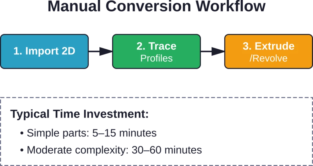
The Basic Workflow
Import the 2D drawing file (DWG, DXF, PDF, or image) into the CAD environment. Trace critical profiles and cross-sections on construction planes. Use extrusion, revolution, lofting, and sweeping operations to generate 3D volumes from the 2D profiles.
For simple prismatic parts, extrusion handles most geometry. Cylindrical features need revolution around an axis. Complex organic shapes require lofting between multiple cross-sectional profiles. Swept features follow a path curve.
Now, this is where it gets interesting. Accuracy depends entirely on how well the original 2D drawing conveys depth information. Orthographic projections with clear dimensions translate cleanly. Isometric views without dimensions require interpretation and measurement—introducing potential errors.
AutoCAD 2D Drawing and 3D Modeling
AutoCAD remains the industry standard for 2D drafting, which makes it a natural starting point for conversion. The software includes robust 3D modeling capabilities, though the interface separation between 2D and 3D workspaces can feel abrupt for users primarily trained in drafting.
The typical process: open the 2D DWG file, switch to 3D modeling workspace, and use EXTRUDE, REVOLVE, LOFT, and SWEEP commands on closed polylines or regions. AutoCAD’s advantage lies in file compatibility—no import/export losses when working with native DWG files.
FreeCAD: Converting 2D Plans to 3D
FreeCAD offers an open-source alternative with a distinct parametric modeling philosophy. The Draft Workbench handles 2D geometry import (SVG, DXF, DWG), while the Part Design Workbench builds 3D features.
The learning curve is steeper than commercial alternatives, but the cost is right—zero. Community discussions emphasize starting with simple extrusion exercises before attempting complex conversions. The software’s constraint-based approach rewards careful planning but punishes haphazard sketching.
ZW3D: Converting 2D Drawings to 3D Models Easily
ZW3D markets itself specifically around efficient 2D-to-3D workflows, combining hybrid modeling (solid and surface), direct editing, and integrated CAM. The platform includes dedicated tools for recognizing standard features from 2D views and semi-automating their 3D construction.
According to ZWSOFT’s documentation, the conversion process emphasizes speed and cost-effectiveness for manufacturing applications. The software can interpret orthographic projection sets (front, top, side views) and suggest appropriate 3D operations—though final accuracy still requires engineer review.
ZW3D’s all-in-one nature (CAD/CAE/CAM) appeals to shops that want to go directly from converted models to toolpath generation without switching platforms. The tradeoff: less market penetration than AutoCAD or SolidWorks, potentially limiting file exchange with partners.
Automated and AI-Assisted Conversion
The idea of feeding a 2D drawing into software and receiving a ready-to-use 3D model has obvious appeal. Research in geometric deep learning and shape reconstruction explores exactly this problem—but practical production tools remain limited.
IEEE research surveys on geometric deep learning for computer-aided design examine how neural networks can learn 3D shape representations from 2D projections. Academic work on shape reconstruction from magnetic resonance imaging demonstrates that AI can infer 3D geometry from 2D slices—though medical imaging provides far more standardized input than engineering drawings.
The challenge for general-purpose engineering drawings: ambiguity. A single orthographic view can correspond to infinite possible 3D shapes. Even complete orthographic projection sets (six views) can be interpreted multiple ways without additional conventions and dimensioning standards.
That said, specialized domains show promise. Automated identification of sheet metal parts using deep learning leverages the constrained geometry of bent metal—a domain where assumptions about constant thickness and standard bend radii reduce ambiguity significantly.
Current State of AI Conversion Tools
As of early 2026, no widely adopted commercial tools offer fully automated 2D-to-3D conversion for arbitrary mechanical drawings. Experimental platforms and research prototypes exist, but they require carefully controlled input formats and often produce geometry needing extensive cleanup.
The practical limitation: training data. AI systems need thousands of paired examples (2D drawing + corresponding validated 3D model) to learn the conversion mapping. Most companies treat their CAD libraries as proprietary assets, limiting the availability of large-scale training datasets.
Convert 2D Drawings into Coordinated 3D BIM Models
2D to 3D CAD conversion helps teams move from static drawings into coordinated BIM workflows. Powerkh supports project delivery with BIM conversion, model development, and technical documentation services.
Need 2D to 3D Conversion Support?
Talk with Powerkh to:
- convert CAD drawings into BIM models
- prepare models for coordination workflows
- support documentation and design updates
- improve collaboration across project teams
Review your CAD-to-BIM requirements with Powerkh.
Choosing the Right Conversion Approach
Selection criteria come down to four factors: starting material quality, required accuracy, available software, and time constraints.
| Scenario | Recommended Method | Typical Time |
|---|---|---|
| Clean DWG with dimensions | Manual in native software | 15–45 min |
| Scanned paper drawing | Trace and extrude | 1–3 hours |
| PDF orthographic views | Import reference, rebuild | 30–90 min |
| Simple sheet metal part | ZW3D or SolidWorks tools | 10–30 min |
| Complex organic shapes | Manual lofting/surfacing | 2+ hours |
When Manual Methods Win
For one-off conversions or parts requiring high accuracy, manual reconstruction by a skilled CAD operator produces the most reliable results. The engineer can apply domain knowledge—recognizing standard features, applying manufacturing constraints, and making informed decisions about ambiguous dimensions.
Manual methods also preserve design intent. Automatically extruded geometry might be geometrically correct but lack the parametric structure needed for future modifications. A manually built model with proper constraints and feature relationships supports downstream design changes.
When to Push for Automation
High-volume conversion projects—digitizing an entire legacy drawing archive, for example—justify investment in specialized tools or even custom AI development. The per-unit time savings compound across hundreds or thousands of parts.
Standardized parts from limited domains (fasteners, structural steel shapes, pipe fittings) also benefit from automation. The constrained geometry space makes feature recognition tractable, and catalog parts rarely need parametric editability.
Practical Tips for Efficient Conversion
Experienced CAD users develop workflows that minimize rework and maximize accuracy. These practices apply regardless of specific software choice.
Start with Scale Verification
Imported 2D drawings—especially scanned images or PDFs—often lose dimensional accuracy during format conversion. Before building any 3D geometry, verify scale by measuring a known dimension in the CAD environment against the drawing specification.
Most CAD packages include calibration tools: measure a line of known length, then apply a scale factor to correct the imported geometry. Skipping this step leads to hours of wasted work building geometry at the wrong size.
Organize Construction Geometry
Separate reference 2D geometry, construction sketches, and final 3D features into distinct layers or feature groups. This organization makes it easy to hide reference drawings once conversion completes, and simplifies troubleshooting when features fail to regenerate.
Use consistent naming conventions for sketches and features. “Base_Extrude”, “Side_Cut”, “Mounting_Holes” beat “Sketch1”, “Extrude3”, “Cut7” when you need to modify the model six months later.
Work in Stages with Validation Points
Build and verify major volumes before adding detailed features. Extrude the base shape, confirm overall dimensions, then add holes, fillets, and chamfers. This staged approach catches major errors early, before investing time in details that might need deletion.
Cross-check measurements against the original drawing at each stage. It’s easier to fix a 1mm dimension error in a base sketch than to compensate for it across twenty downstream features.
Common Challenges and Solutions
Even experienced users hit predictable obstacles during conversion. Recognizing these patterns speeds troubleshooting.
Ambiguous Depth Information
Single-view drawings or isometric sketches without dimensions leave depth ambiguous. The solution: contact the drawing source for clarification, measure physical parts when available, or apply standard conventions (equal spacing, symmetric features) to make reasonable assumptions.
Document assumptions in the CAD model—add comments or dimension labels noting “Assumed symmetric” or “Depth estimated from isometric angle.” This prevents future confusion when someone questions the geometry.
Inconsistent Units and Scale
Mixing metric and imperial dimensions, or encountering drawings without explicit unit labels, causes endless headaches. Always establish unit standards before starting conversion, and configure the CAD environment to match the drawing’s native units.
When unit ambiguity persists, look for context clues: thread callouts (M6 indicates metric), standard part sizes (0.25-20 UNC indicates imperial), or company location (European companies typically use metric).
Poor Quality Scans
Faded photocopies, skewed scans, and low-resolution images make accurate tracing difficult. Image preprocessing helps: adjust contrast, apply sharpening filters, and use perspective correction tools to square up skewed views before importing into CAD.
For critical dimensions, don’t rely on pixel measurements from poor scans. Use the scan as a rough guide for feature placement, but model to explicit dimensions from the drawing’s text annotations.
Future Directions: AI and Automated Conversion
The question isn’t whether AI will eventually automate 2D-to-3D conversion—it’s when the technology reaches production-ready reliability. Current research shows promising trajectories but significant remaining challenges.
Deep Learning Approaches
Convolutional neural networks can learn to recognize engineering features (holes, slots, bosses) from 2D representations. The architecture challenge involves encoding geometric constraints and manufacturing knowledge into the network structure.
Research on automated identification of sheet metal parts demonstrates success in constrained domains. Extending these techniques to general mechanical parts requires much larger training datasets and more sophisticated network architectures.
Hybrid Human-AI Workflows
Near-term practical systems will likely combine AI feature recognition with human validation and correction. The AI suggests possible 3D interpretations, engineers select the correct option or adjust parameters, and the system learns from these corrections.
This approach addresses the training data limitation: the system improves continuously as users correct its mistakes, gradually reducing the human intervention needed for similar parts.
Domain-Specific Solutions
Rather than attempting general-purpose conversion, specialized tools for specific industries (sheet metal fabrication, injection molding, structural steel) can leverage domain constraints to achieve higher accuracy with less training data.
These vertical solutions will likely arrive first, proving the technology before general-purpose systems emerge.
Conclusion
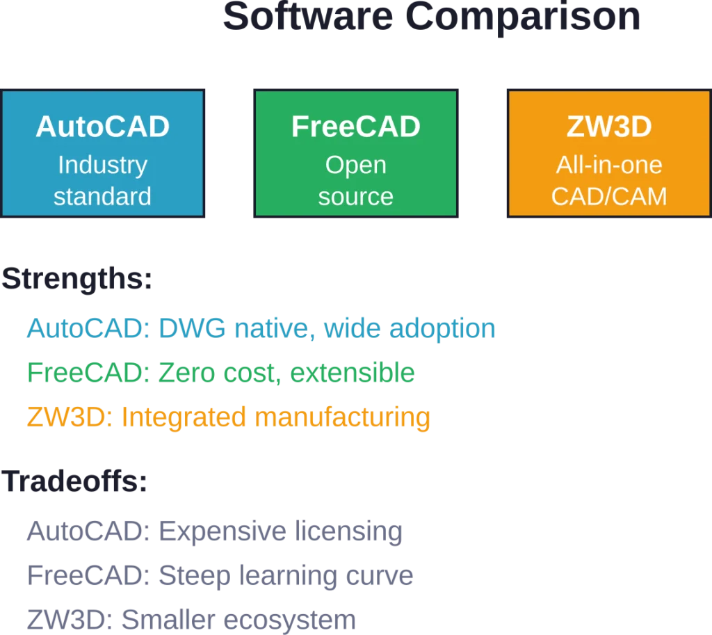
2D to 3D CAD conversion remains primarily a manual skill in 2026, requiring solid understanding of CAD software, engineering drawings, and manufacturing processes. AutoCAD, FreeCAD, and ZW3D each offer viable conversion pathways, with selection depending on budget, existing software investments, and workflow integration needs.
The time investment—typically 15 minutes to several hours per part—pays off when dealing with legacy components, supplier limitations, or field-modified parts. Manual methods deliver reliable accuracy when handled by skilled operators, while emerging AI approaches promise future automation for high-volume digitization projects.
For engineers facing conversion projects today, the practical advice boils down to this: choose software matching your existing ecosystem, verify scale rigorously, work in validated stages, and document assumptions clearly. Check current CAD vendor documentation for the latest conversion tools and features—capabilities evolve rapidly.
Start with simpler parts to build proficiency, then tackle complex geometry once fundamental workflows feel natural. The skill compounds over time, making each subsequent conversion faster and more accurate than the last.
Frequently Asked Questions
Simple prismatic parts with clear dimensions convert in 15–30 minutes. Moderate complexity components with multiple features require 30–90 minutes. Complex assemblies or parts with ambiguous geometry can take 2–4 hours or more, depending on detail level and required accuracy.
Fully automatic conversion remains limited in 2026. Some CAD packages offer semi-automated tools for recognizing standard features in orthographic projections, but these require clean input and typically need manual review and correction. AI-assisted tools show promise for constrained domains like sheet metal but aren’t production-ready for general mechanical parts.
AutoCAD excels for users already working with DWG files, offering native format compatibility and robust 3D tools. FreeCAD provides a cost-free option with parametric modeling capabilities, though with a steeper learning curve. ZW3D integrates CAD and CAM for manufacturing-focused workflows. The best choice depends on existing software investments, budget, and specific workflow requirements.
DWG and DXF files preserve vector geometry and dimensions, making them ideal starting points. PDF drawings work if they contain vector data rather than raster images. Scanned images (PNG, JPG, TIFF) require manual tracing since they lack dimensional data. STEP and IGES files already contain 3D geometry and don’t require conversion.
Accuracy depends on source drawing quality and operator skill. With clear dimensions and orthographic views, experienced users achieve tolerances matching the original drawing specification—typically within 0.01–0.1mm for precision parts. Ambiguous drawings or poor-quality scans reduce accuracy significantly, sometimes requiring physical part measurement for validation.
Basic CAD proficiency is essential—understanding sketches, constraints, extrusions, and revolutions. Engineers familiar with reading engineering drawings convert more accurately since they recognize standard conventions and can interpret ambiguous geometry. Most users develop conversion skills through practice rather than formal training, starting with simple parts and progressing to complex assemblies.
Not yet for general mechanical parts. Research in geometric deep learning shows promise, and specialized tools for constrained domains (sheet metal, standard fasteners) demonstrate feasibility. But ambiguity in general engineering drawings—where multiple 3D shapes can produce identical 2D projections—remains a fundamental challenge. Hybrid approaches combining AI suggestion with human validation represent the near-term practical path.