Quick Summary: Rebar shop drawings are detailed technical documents that translate structural engineering plans into precise fabrication and installation instructions for reinforcing steel bars in concrete structures. These drawings specify exact bar sizes, quantities, bending dimensions, placement locations, lap splice lengths, and assembly details. They serve as the critical link between design intent and on-site execution, ensuring structural integrity while minimizing material waste and installation errors.
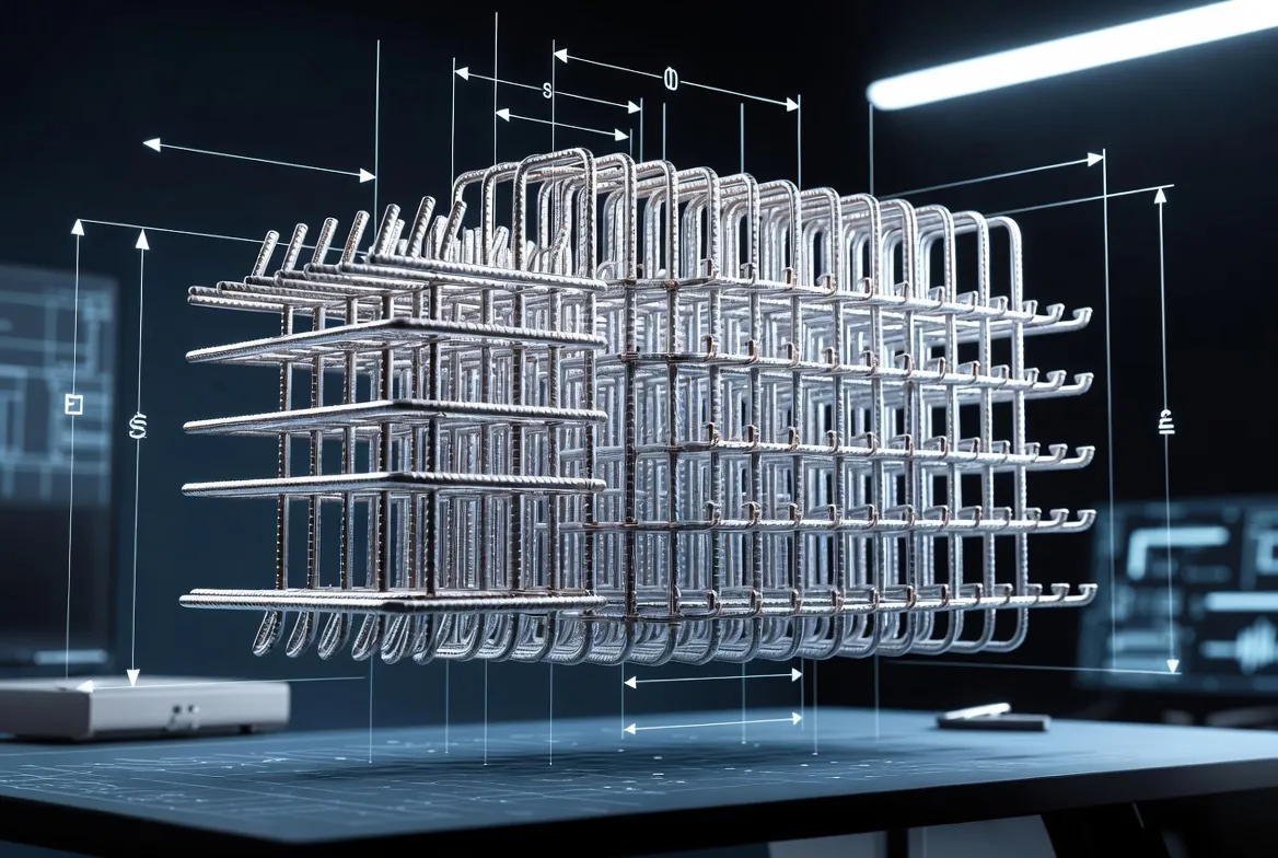
Walk onto any major construction site and there’s a good chance someone’s studying a set of technical drawings. But these aren’t the architect’s pretty renderings. They’re rebar shop drawings—the blueprint that tells fabricators and installers exactly how to place every single steel bar that’ll keep that concrete structure from crumbling.
Without these drawings, reinforced concrete construction would be chaos. Bars would get bent wrong, placed in the wrong spots, or cut to incorrect lengths. That’s not just inefficient—it’s dangerous.
Understanding Rebar Shop Drawings: The Foundation
A rebar shop drawing is a specialized construction document that provides comprehensive details for fabricating and installing reinforcing steel bars in concrete structures. According to the Concrete Reinforcing Steel Institute (CRSI), these drawings are developed following standards from organizations like the American Concrete Institute (ACI) and the American National Standards Institute (ANSI).
Here’s the thing though—structural engineers don’t create these. Engineers produce structural drawings that show the overall reinforcement strategy. Rebar detailers then take those engineering plans and transform them into shop-level detail.
The drawings show every bar mark, size, quantity, bending dimension, and placement location. They include schedules, section views, and assembly details that fabrication shops use to cut and bend bars, and that field crews use to install them correctly.
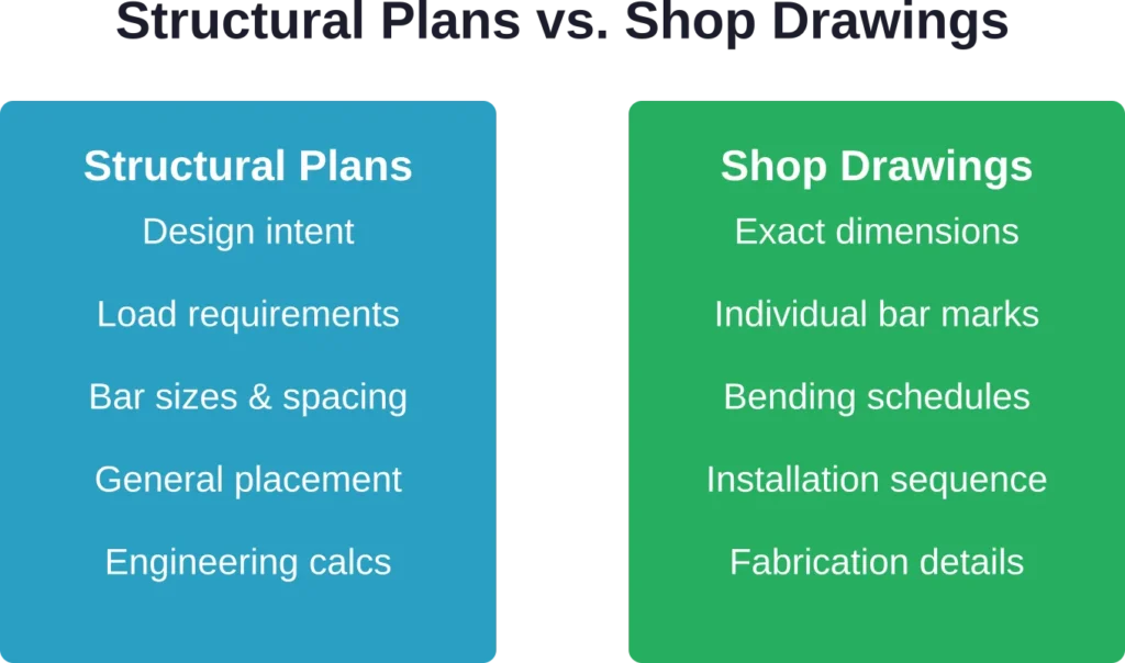
How Shop Drawings Differ From Structural Plans
Structural plans communicate design intent. Shop drawings communicate execution details. An engineer might show that a beam needs #5 bars at 12-inch spacing. The shop drawing will show each individual bar with a unique identifier (B1, B2, B3), exact cut lengths, bend angles, hook dimensions, and precisely where each piece goes relative to the formwork.
This level of detail matters because concrete doesn’t give second chances. Once it’s poured, the steel is locked in place.
Essential Components of Rebar Shop Drawings
Every rebar shop drawing contains specific elements that fabricators and installers rely on. Miss one component and the drawing becomes unusable.
Bar Mark System
Each group of identical bars gets a unique identifier called a bar mark. These marks (typically alphanumeric like F1, B12, or C3) appear on the drawings and get tagged to physical bundles in the fabrication shop. This tracking system prevents mix-ups during delivery and installation.
Bar Bending Schedules
The bending schedule is a tabulated list showing every bar mark with its size, quantity, length, shape code, and bending dimensions. This table tells the fabrication shop exactly how to process each bar. One common format includes columns for mark number, bar diameter, total length, number of pieces, and detailed dimensions for each bend or hook.
Placement Plans and Sections
Plan views show bar placement from above—where bars run in slabs, footings, and mat foundations. Section cuts reveal what’s happening vertically—how bars are arranged in walls, columns, and beam depths. Elevation views show reinforcement along vertical or sloped surfaces.
These views work together. A plan might show that bars run north-south at 8-inch spacing, while a section reveals they’re positioned 3 inches from the top surface with 2-inch clear cover at the bottom.
Splice and Anchorage Details
Reinforced concrete structures need to behave monolithically. That means bars must be properly spliced to transmit forces through the structure. According to CRSI standards, lap splices—where two bars overlap to create continuity—are the predominant method. Shop drawings specify lap lengths based on concrete strength, rebar grade, size, and spacing requirements from ACI code.
Contact splices, where bars touch and are wired together, are preferred because they resist displacement during concrete placement. The drawings will call out which bars get lapped, the required overlap length, and whether contact is specified.
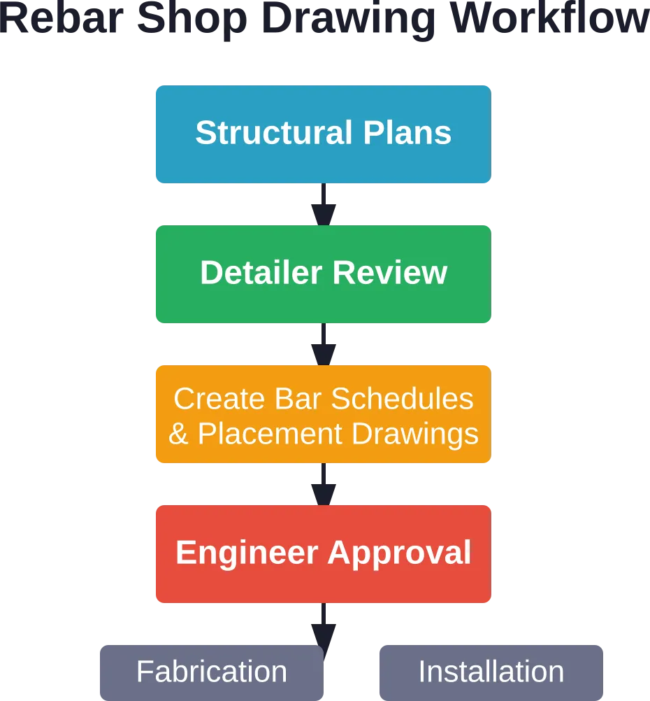
The Shop Drawing Creation Process
Creating accurate rebar shop drawings isn’t a one-person job. It’s a collaborative process involving multiple reviews and iterations.
Step 1: Review Structural Drawings
Detailers start with the structural engineer’s plans and specifications. They identify all reinforcement requirements, note special details, and flag any conflicts or unclear areas. Questions get sent back to the engineer before detailing begins.
Step 2: Develop Bar Lists and Schedules
Detailers assign bar marks and build the bending schedules. They calculate exact cut lengths, accounting for hooks, bends, and the geometry of each shape. Modern detailing software can automate much of this, but experienced detailers verify the output because software doesn’t catch every constructability issue.
Step 3: Create Placement Drawings
Using CAD software or Building Information Modeling (BIM) tools like Tekla Structures, detailers create the plan views, sections, and details. Industry-leading software allows creation of data-rich 3D models where every bar contains material grades, part marks, and assembly data.
Traditional 2D workflows using AutoCAD remain common and ensure compatibility with client-specific templates and existing drawing libraries.
Step 4: Engineer Review and Approval
Draft shop drawings go to the structural engineer for review. Engineers verify that the detailing matches design intent, check splice locations, confirm cover dimensions, and ensure bars won’t interfere with other trades’ work. Approved drawings get stamped and returned.
Step 5: Fabrication and Installation
Approved drawings go to the fabrication shop where bars are cut, bent, and bundled according to the schedules. Bar tags reference the shop drawing mark numbers. On site, installers reference the placement drawings to position each bundle correctly before concrete placement.
Prepare Rebar Shop Drawings for Fabrication and Site Use

Rebar shop drawings are used to guide reinforcement fabrication and installation on concrete construction projects. Powerkh supports structural teams with reinforcement detailing, BIM coordination, and technical documentation workflows.
Need Rebar Shop Drawing Support?
Talk with Powerkh to:
- prepare detailed reinforcement drawings
- support fabrication and installation workflows
- coordinate rebar with structural models
- improve documentation accuracy before construction
Discuss reinforcement detailing and shop drawing requirements with Powerkh.
Why Rebar Shop Drawings Matter
The consequences of poor or missing shop drawings ripple through a project. Here’s what’s at stake.
Structural Safety and Code Compliance
Properly detailed and placed reinforcement is fundamental to structural integrity. ACI 318 Building Code Requirements for Structural Concrete and AISC standards establish minimum requirements for bar spacing, cover, development length, and splice locations. Shop drawings translate these code requirements into field-executable instructions.
According to CRSI, which operates as an ANSI-approved Standards Development Organization, the scope of standards activities includes design, detailing, fabrication, placement, and construction of assemblies with steel reinforcement. Deviating from approved shop drawings can result in code violations and compromise structural performance.
Material Optimization and Waste Reduction
Accurate shop drawings minimize waste. Detailers optimize cutting patterns to get the most bars from standard stock lengths. They identify opportunities to standardize bar sizes across similar elements. These efficiencies translate directly to cost savings.
In specialized applications like voided slabs—where concrete is removed from the middle of the slab—proper reinforcement detailing can reduce dead load by as much as 35% while maintaining structural efficiency, according to CRSI terminology references.
Clash Detection and Coordination
Modern BIM-based detailing allows clash detection before fabrication begins. Detailers can identify conflicts between rebar and mechanical/electrical/plumbing systems, structural steel connections, or embedded items. Resolving these conflicts on paper is infinitely cheaper than discovering them with a concrete truck waiting on site.
Installation Efficiency
Clear, accurate shop drawings let field crews work faster and with fewer errors. When every bar is clearly marked and shown in context, installers don’t waste time interpreting ambiguous plans or making field decisions that should have been resolved during detailing.
Common Rebar Shop Drawing Elements Explained
Understanding the terminology and symbols makes shop drawings readable.
| Element | Description | Typical Use |
|---|---|---|
| Bar Mark | Unique identifier for each bar group (e.g., F1, B12) | Tracking and installation reference |
| Lap Splice | Region where two bars overlap for continuity | Extending reinforcement length |
| Development Length | Embedment length needed to develop bar strength | Anchorage at bar terminations |
| Clear Cover | Minimum concrete thickness over outermost steel | Corrosion protection and fire resistance |
| Stirrups/Ties | Closed loops that confine longitudinal bars | Shear reinforcement and bar positioning |
| Hook | 90° or 180° bend at bar end | Anchorage in limited space |
Reading Bar Callouts
A typical bar callout looks like: “#5 @ 12″ O.C.” This means number 5 bars (5/8-inch diameter) placed at 12-inch spacing measured on center. Another common format: “10-#6” means ten pieces of number 6 bars.
Shape codes use standard designations. A “90” might indicate a standard 90-degree hook. A “180” indicates a hairpin or U-bar. Detailers follow shape code standards to ensure consistency across projects and fabricators.
Software and Technology in Rebar Detailing
The detailing process has evolved significantly from hand-drawn plans on vellum.
2D CAD Systems
AutoCAD remains widely used for traditional 2D rebar detailing. It allows for lightning-fast revisions when site conditions shift and integrates perfectly with contractors who prefer traditional workflows. The software ensures compatibility with client-specific templates and architectural backgrounds.
3D BIM Platforms
Tekla Structures represents the advanced end of BIM software for structural detailing. Every element in a Tekla model is data-rich—a beam contains material grades, part marks, assembly data, and even carbon footprint information. These models reach Level of Development 400 and 500, containing every bolt, weld, and rebar item necessary for direct fabrication.
The truly constructible BIM approach lets detailers model multi-material projects with steel, concrete, timber, and other materials in one coordinated environment. Automatic clash detection prevents conflicts before they reach the field.
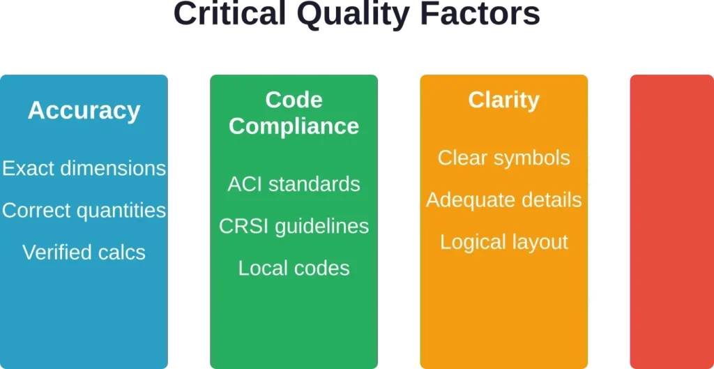
Best Practices for Quality Shop Drawings
Producing shop drawings that actually work requires attention to detail and adherence to industry standards.
Follow Standard Conventions
Use consistent symbology, line weights, and notation systems. CRSI publishes standard detailing practices that most fabricators and contractors understand. Reinventing notation systems creates confusion and errors.
Coordinate Early and Often
Engage with the structural engineer during the detailing process, not just at final review. Early coordination catches design issues before they become expensive problems. Similarly, coordinate with other trades—especially MEP contractors—to identify conflicts.
Verify Constructability
Ask whether bars can actually be placed as shown. Can installers physically position the reinforcement within the formwork? Do bar intersections create congestion that’ll prevent proper concrete consolidation? Experienced detailers think like field crews.
Include Adequate Details
Don’t assume field crews will “figure it out.” Complex intersections, special anchorage conditions, and congested areas need enlarged details. Show exactly how bars overlap, where chairs and supports go, and how to sequence installation.
Maintain Clear Documentation
Include revision tracking, clear title blocks, drawing indices, and reference to applicable codes and standards. When changes occur (and they will), document what changed, when, and why. This creates an audit trail that protects all parties.
Common Mistakes to Avoid
Even experienced detailers can fall into these traps.
Insufficient Cover Dimensions
Failing to maintain minimum cover over reinforcement leads to corrosion problems and fire resistance issues. Always verify cover requirements from the structural drawings and ensure bar placement provides the specified protection.
Incorrect Splice Locations
Placing splices in high-stress areas or failing to stagger them properly creates weak points. ACI code prohibits splicing all bars in a section at the same location. Alternate splice positions to maintain structural continuity.
Ignoring Bar Spacing Limits
Bars placed too close together prevent concrete from flowing between them, creating voids. Bars spaced too far apart don’t control cracking effectively. Both minimum and maximum spacing requirements exist for good reasons.
Missing Coordination Notes
Failing to note special installation sequences, temporary support requirements, or coordination with other trades leaves field crews guessing. When something’s critical to success, call it out explicitly.
Frequently Asked Questions
Rebar detailing is the overall process of analyzing structural plans and creating detailed reinforcement documentation. Rebar shop drawings are the actual deliverable documents produced through that detailing process. The terms are often used interchangeably, but detailing encompasses the entire workflow while shop drawings refer specifically to the final drawings and schedules.
Specialized rebar detailers create shop drawings, typically working for steel fabricators, detailing service companies, or general contractors. These professionals have expertise in reinforced concrete construction, fabrication processes, and industry standards. They’re not structural engineers—engineers design the reinforcement system, detailers translate that design into fabrication-ready instructions.
Most commercial, industrial, and infrastructure projects require formal shop drawings. Small residential projects might use simplified bar lists or work directly from structural plans. The complexity of the structure and project specifications determine whether full shop drawing submittal is required. When in doubt, project specifications will state the requirement explicitly.
Turnaround time varies with project complexity and size. Simple foundations might take 24-48 hours for initial drafts. Large commercial buildings or complex structures can require several weeks. Some detailing services advertise 24-48 hour initial turnaround for standard projects, but this depends on the scope and whether all necessary information is available upfront.
AutoCAD remains the standard for 2D rebar detailing due to its flexibility and universal file compatibility. For 3D BIM-based detailing, Tekla Structures is widely considered the industry leader, creating data-rich models with Level of Development 400-500 detail. Other options include RebarCAD (an AutoCAD add-on) and various specialized rebar detailing modules within broader BIM platforms.
Yes, revisions happen frequently due to field conditions, design changes, or coordination issues discovered during construction. However, any revision to an approved shop drawing must go back through the engineer for review and re-approval before implementation. Proper revision tracking and documentation is essential to avoid confusion about which drawing version is current.
Absolutely. Shop drawings must be reviewed and approved (or approved with noted corrections) by the structural engineer of record before fabrication begins. This review confirms that the detailing matches design intent and satisfies code requirements. Working from unapproved shop drawings exposes all parties to liability if structural problems arise.
Final Thoughts
Rebar shop drawings are the unsung heroes of concrete construction. They bridge the gap between engineering theory and field reality, transforming design calculations into physical reinforcement that’ll support loads for decades.
Quality shop drawings prevent costly mistakes, optimize material use, ensure code compliance, and make installation faster and safer. In an industry where errors are expensive and safety is paramount, the precision of shop drawings isn’t optional—it’s fundamental.
Whether working on a simple foundation or a complex high-rise, the investment in professional rebar detailing and shop drawing preparation pays dividends throughout the construction process and the structure’s entire service life.
Need expert rebar shop drawings for an upcoming project? Work with qualified detailing professionals who understand both the technical standards and the practical realities of reinforced concrete construction.