
Quick Summary: Level of Accuracy (LOA) in BIM defines how closely a 3D model matches real-world conditions, typically based on laser scan or reality capture data. LOA specifications—ranging from LOA 10 (approximate massing) to LOA 50 (field-verified precision)—guide scan-to-BIM projects by setting geometric tolerance and detail expectations, ensuring model reliability for construction, fabrication, and facility management phases.
Reality capture technologies—laser scanning, photogrammetry, and mobile mapping—have transformed how the AEC industry documents existing conditions. But scanning a building isn’t enough. The real challenge? Translating that point cloud into a BIM model that’s accurate enough for its intended purpose.
That’s where Level of Accuracy (LOA) comes in.
Unlike Level of Development (LOD), which describes design progression in new construction, LOA specifications address geometric fidelity in as-built and scan-to-BIM workflows. Think of it as a contract between the scan team, modelers, and project stakeholders about how precise the digital representation will be.
Here’s the thing though—misunderstanding LOA causes problems. Over-model and budgets balloon. Under-model and fabrication errors pile up on-site.
What is Level of Accuracy in BIM?
Level of Accuracy (LOA) is a specification framework developed by the U.S. Institute of Building Documentation (USIBD) to define the geometric precision and tolerance of BIM elements derived from reality capture data. It answers one critical question: how closely does this model element match the actual built condition?
LOA applies specifically to existing conditions modeling—situations where laser scans, point clouds, or other survey data inform the BIM geometry. The specification sets clear tolerance ranges (measured in millimeters) that govern how much deviation is acceptable between the physical object and its digital twin.
The USIBD framework breaks LOA into five distinct levels, each with defined tolerance bands and typical use cases. The standard recognizes six levels of development (LOD 100, 200, 300, 350, 400, 500) in new construction LOD frameworks, and industry data shows that 80 to 90 percent of model elements should reach LOD 350 for effective coordination.
Real talk: LOA isn’t about making every detail perfect. It’s about making the right details accurate enough for the next phase of work.
The Five LOA Levels Explained
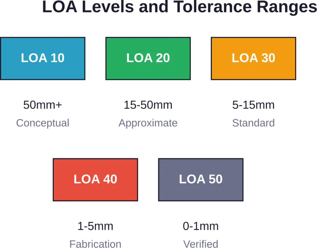
The USIBD Level of Accuracy specification defines five distinct accuracy bands, each suited to different project phases and documentation needs.
LOA 10: Conceptual Representation (50mm – User Defined)
This level provides basic massing and approximate geometry. Dimensions and shapes are generalized, suitable for feasibility studies and early planning when precise measurements aren’t critical. Tolerances can exceed 50mm depending on project requirements.
LOA 20: Approximate Geometry (15mm – 50mm)
Elements are modeled in their generalized form with approximate locations. This level works for early design stages where spatial relationships matter more than exact dimensions. It’s common in renovation projects during initial assessment.
LOA 30: Measured Survey (5mm – 15mm)
Now things get serious. Elements are modeled to actual size, shape, and placement based directly on scan data. LOA 30 represents the standard for most scan-to-BIM projects—balancing accuracy with modeling efficiency. This level supports coordination, clash detection, and design development.
LOA 40: Fabrication Precision (1mm – 5mm)
High-detail modeling with precise element representation and connections. LOA 40 supports fabrication drawings, shop drawings, and construction where tight tolerances prevent costly rework. Expect significantly more modeling time and correspondingly higher costs.
LOA 50: Verified As-Built (0mm – 1mm)
The tightest tolerance band, fully aligned with field-verified conditions. This level is essential for facility management, equipment installation with millimeter clearances, and documentation requiring survey-grade accuracy. LOA 50 typically involves additional field verification beyond the original scan.
LOA vs LOD: Understanding the Difference
Confusion between Level of Accuracy (LOA) and Level of Development (LOD) is common. But they measure different things.
LOD—originally developed by the AIA and refined by organizations like BIMForum—describes how much design information a model element contains. LOD 100 represents conceptual design. LOD 500 represents a verified as-built or as-maintained model. LOD tracks design progression from schematic through construction documentation in new construction projects.
LOA, on the other hand, measures geometric precision relative to existing conditions. It applies when reality capture informs the model. LOA tells stakeholders how tightly the digital model matches physical measurements.
Here’s a practical example: A structural steel connection might be modeled to LOD 400 (highly detailed, with fabrication-level information) but only LOA 30 accuracy (5-15mm tolerance from scan data). The detail is there; the geometric fidelity matches survey-grade documentation needs, not fabrication tolerances.
The short answer? LOD = information richness and design intent. LOA = geometric fidelity to reality.
| Aspect | Level of Development (LOD) | Level of Accuracy (LOA) |
|---|---|---|
| Primary Focus | Design information and detail | Geometric precision vs. physical reality |
| Project Type | New construction and design | Existing conditions and scan-to-BIM |
| Data Source | Design intent, specifications | Reality capture (laser scans, point clouds) |
| Measurement Unit | Information content (qualitative) | Dimensional tolerance (millimeters) |
| Standards Body | AIA, BIMForum | USIBD |
How Scan Quality Affects LOA
The accuracy of your BIM model can’t exceed the quality of your source data. Period.
Laser scanning and photogrammetry introduce their own tolerances. Scanner specifications, registration errors, point cloud density, environmental conditions—all these factors compound. Even high-end terrestrial laser scanners accumulate error across multiple setups and long sightlines.
Testing from Purdue University on infrastructure BIM standards revealed that automated quality assurance tools achieved 91% accuracy on drainage components and 100% accuracy on concrete pavement in IFC model validation. But that presupposes clean, well-registered scan data feeding the modeling process.
Poor scan quality manifests in several ways: occlusions create data gaps, reflective surfaces produce noise, insufficient overlap between scan positions introduces registration drift. Modelers then face impossible choices—guess at hidden geometry or leave elements out entirely.
That’s why LOA specifications exist. They set realistic expectations based on achievable survey accuracy, not theoretical perfection.
Common Scan Quality Issues
- Registration drift: Accumulated error across multiple scan positions, especially in large facilities without survey control
- Occlusions and shadows: Furniture, equipment, or structural elements blocking line-of-sight to surfaces
- Surface reflectivity: Glass, polished metal, and dark surfaces that absorb or scatter laser returns
- Point cloud density: Insufficient resolution for capturing small features or complex geometry
- Environmental interference: Vibration, temperature gradients, or atmospheric conditions affecting measurements
Get Accurate BIM Models from Verified Site Conditions
Powerkh supports project teams with laser scanning, point cloud processing, and BIM modelling based on verified existing conditions. Its services help teams improve model accuracy during design, coordination, and construction stages.
Need Support with Existing Conditions and BIM Accuracy?
Talk with Powerkh to:
- create BIM models from laser scan data
- improve model accuracy before coordination starts
- verify existing building conditions
- support renovation and retrofit projects with reliable site information
Contact Powerkh for a project review and consultation.
Choosing the Right LOA for Your Project
Sound familiar? Project starts, scanning happens, modeling begins—and nobody agreed on the required accuracy level until the client rejects deliverables for being “not detailed enough.”
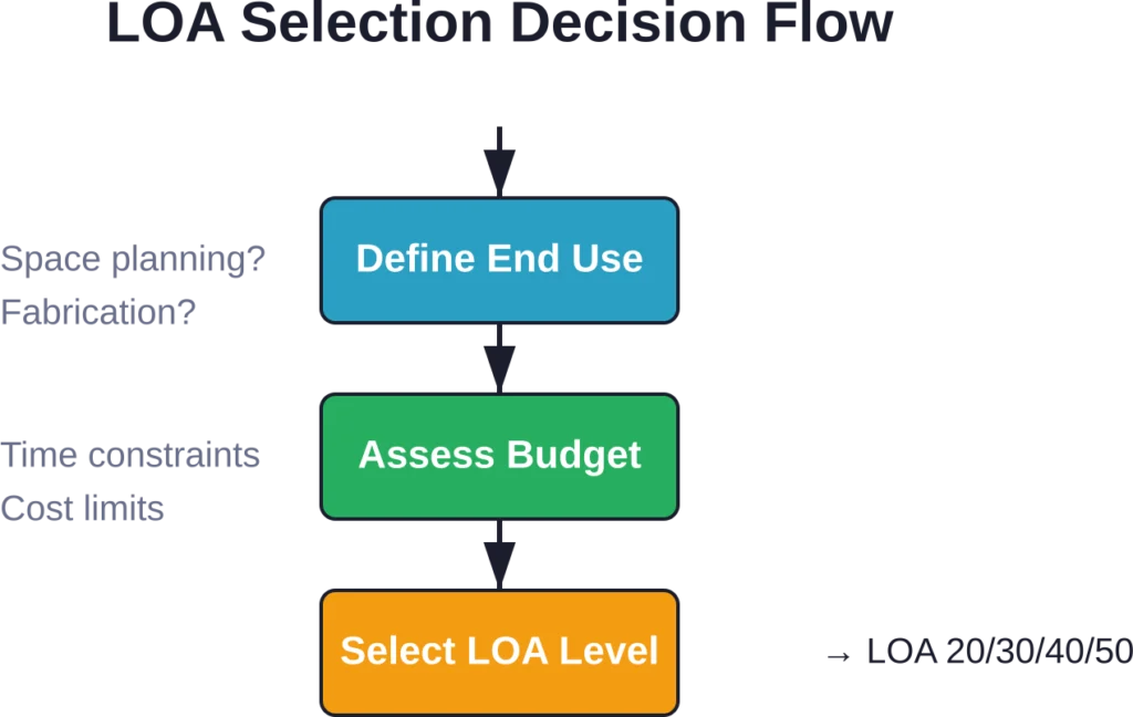
Defining LOA requirements early prevents that mess. But how do teams choose?
Start with the end use. Facility management for a commercial office? LOA 30 typically suffices for space planning and systems coordination. MEP fabrication in a hospital renovation? LOA 40 or LOA 50 becomes necessary to ensure equipment fits within tight ceiling cavities.
Budget and schedule matter too. Higher LOA levels demand more scan time (denser coverage, tighter registration), more modeling time (smaller tolerances, more validation), and more quality control. The cost difference between LOA 30 and LOA 50 can easily double or triple.
Most commercial and institutional scan-to-BIM projects typically use LOA 20 to LOA 30 for renovation and retrofit work. Infrastructure and industrial facilities—where millimeter clearances affect operations—push toward LOA 40 and LOA 50.
Typical LOA Applications by Project Type
| Project Type | Common LOA Level | Why This Level? |
|---|---|---|
| Commercial Tenant Improvement | LOA 20 – LOA 30 | Space planning and coordination; tight tolerances not critical |
| Hospital MEP Retrofit | LOA 40 | Tight ceiling cavities; equipment clearances; fabrication coordination |
| Historic Preservation | LOA 30 – LOA 40 | Documentation accuracy for conservation and restoration work |
| Industrial Equipment Installation | LOA 40 – LOA 50 | Millimeter clearances; operational safety; equipment anchoring |
| Facility Management (existing) | LOA 30 | Asset locations; space allocation; maintenance access |
LOA and the USIBD Specification Framework
The U.S. Institute of Building Documentation released LOA Specification Version 3.1, establishing a standardized language for reality capture deliverables. The specification provides detailed guidance on tolerance measurement, element classification, and quality control procedures.
What’s new in Version 3.1? The update refines tolerance definitions, expands element categories (architectural, structural, MEP, site), and introduces clearer guidelines for mixed-LOA models—projects where different building systems are modeled to different accuracy levels based on project needs.
The USIBD also offers professional certification programs. LOA-certified professionals demonstrate competency in reality capture workflows, tolerance verification, and specification compliance. For firms competing on scan-to-BIM projects, certification signals capability and reduces client risk.
Adoption matters because it establishes accountability. When contracts reference USIBD LOA specifications, everyone operates from the same playbook. Disputes about “accurate enough” get replaced by measurable tolerances and defined verification procedures.
Quality Control and LOA Verification
Specifying an LOA level means nothing without verification. How do teams confirm that models meet the stated tolerance?
The most rigorous approach: point cloud comparison. Modelers export IFC geometry, register it to the original point cloud, and generate deviation reports showing where model surfaces diverge from scan data. Specialized software automates this process, color-coding elements by deviation magnitude.
Spot checking works for lower LOA levels. Measure critical dimensions in the model, compare them to scan measurements or field verification. Document discrepancies and ensure they fall within the specified tolerance band.
Here’s where it gets interesting. Research on infrastructure BIM indicates that establishing clear success factors and guidelines for openBIM workflows improves coordination. Global infrastructure investment is projected at approximately $94 trillion between 2016 and 2040 drive public agencies to mandate openBIM, recognizing its ability to eliminate waste through better collaboration.
But QA/QC doesn’t stop at geometric accuracy. Teams must also verify that the right elements were modeled. A perfectly accurate model that omits critical equipment or structural members fails its purpose just as badly as one with poor tolerances.
Effective LOA Verification Steps
- Define acceptance criteria upfront: Document tolerance requirements, measurement methods, and sample sizes in the project specification
- Perform iterative checks during modeling: Don’t wait until completion; validate sections as modeling progresses
- Use automated deviation analysis: Point cloud comparison software identifies outliers faster and more comprehensively than manual spot checks
- Document and communicate results: Generate reports showing compliance, flag exceptions, and provide context for deviations
- Field-verify critical elements: For LOA 40 and LOA 50, supplement scans with direct field measurements on key components
Common LOA Misconceptions
Let’s clear up some persistent myths.
Myth: Higher LOA is always better.
Not true. Over-modeling wastes time and budget. LOA 50 precision for a warehouse office build-out? Unnecessary. Match the accuracy to the need.
Myth: LOA is just about dimensions.
LOA encompasses element placement, orientation, geometric fidelity, and tolerance zones. A beam modeled to correct length but misplaced by 50mm doesn’t meet LOA 30, even if its dimensions are accurate.
Myth: Any scan can produce high LOA.
Scan quality, registration accuracy, and point cloud density limit achievable LOA. A quick mobile scan won’t support LOA 50. Scanner selection and field procedures must align with target accuracy.
Myth: LOA and LOD are interchangeable.
As covered earlier, they measure different attributes—geometric precision versus information content. A model can have high LOD with low LOA, or vice versa.
Integration with ISO 19650 and BIM Standards
ISO 19650 provides an international framework for managing information in BIM workflows. It establishes processes for information exchange, defines roles and responsibilities, and sets requirements for collaborative information production.
LOA specifications complement ISO 19650 by addressing the geometric accuracy component often left vague in broader information management standards. When ISO 19650 asks “what information is required and when,” LOA answers “how geometrically accurate must existing conditions elements be.”
Organizations adopting ISO 19650 benefit from incorporating USIBD LOA language into their Employer’s Information Requirements (EIR) and BIM Execution Plans (BEP). This integration ensures that reality capture deliverables meet both information content and geometric accuracy expectations.
For multinational projects, aligning LOA with ISO standards facilitates cross-border collaboration. Consistent terminology reduces misunderstandings when design teams, scan providers, and contractors operate under different national conventions.
Future Trends in LOA and Reality Capture
Reality capture technology evolves quickly. Lidar sensors shrink and become affordable. Photogrammetry algorithms improve. Mobile scanning platforms—robots, drones, handheld devices—proliferate.
As capture becomes faster and cheaper, the bottleneck shifts to modeling and validation. Automation helps: machine learning classifies point cloud objects, automated modeling tools generate geometry from scans, and AI-assisted QA flags deviations.
Expect LOA specifications to expand. Current frameworks focus primarily on architectural and MEP elements. Infrastructure, industrial facilities, and specialty environments (tunnels, power plants, refineries) need domain-specific LOA guidance.
Real-time validation—comparing scan data to models during capture—promises to catch errors earlier. Imagine scanning, modeling, and verifying in a continuous loop rather than sequential phases. That workflow requires tighter integration between capture hardware, modeling software, and QA platforms.
Digital twins push LOA considerations into operations and maintenance. Facilities demand up-to-date models reflecting renovations, equipment changes, and system upgrades. LOA specifications will increasingly govern not just initial documentation but ongoing model currency and accuracy over asset lifecycles.
Frequently Asked Questions
LOA (Level of Accuracy) measures geometric precision—how closely a model element matches physical reality, typically based on scan data. LOD (Level of Development) describes information richness and design detail in new construction models. LOA applies to existing conditions; LOD applies to design intent.
Most commercial and institutional scan-to-BIM projects use LOA 30 (5-15mm tolerance), balancing accuracy with cost and schedule. LOA 40 and LOA 50 are reserved for fabrication-critical or infrastructure work requiring tighter tolerances.
Yes. Mixed-LOA models are common. Structural elements might be modeled to LOA 40 for fabrication coordination, while architectural finishes remain at LOA 30. The key is documenting which systems receive which accuracy level in the project specification.
Scan quality—resolution, registration accuracy, coverage—sets the upper limit on achievable LOA. Poor scans with registration drift or sparse point density can’t support LOA 40 or LOA 50, regardless of modeling effort. Scanner selection and field procedures must align with target LOA.
The USIBD (U.S. Institute of Building Documentation) LOA Specification is the industry-standard framework defining tolerance bands, measurement methods, and element classifications for scan-to-BIM accuracy. Version 3.1, the latest release, provides detailed guidance for specifying and verifying geometric fidelity.
Verification typically involves point cloud comparison—exporting model geometry, registering it to the original scan, and generating deviation reports. Automated software color-codes elements by deviation magnitude. For LOA 40 and LOA 50, field measurements supplement scan-based validation.
Yes. Higher LOA levels require denser scan coverage, tighter registration, more modeling time, and more rigorous QA. The cost difference between LOA 30 and LOA 50 can double or triple. Teams should specify only the accuracy the project actually requires.
Conclusion
Level of Accuracy isn’t just another acronym cluttering BIM conversations. It’s the bridge between physical reality and digital models—a shared language that aligns expectations, prevents disputes, and ensures scan-to-BIM deliverables actually serve their intended purpose.
Whether modeling a hospital renovation, documenting a historic structure, or coordinating MEP systems in a retrofit, understanding LOA levels helps teams make smarter decisions. LOA 30 for most projects. LOA 40 when fabrication precision matters. LOA 50 when millimeter tolerances are non-negotiable.
The USIBD specification provides the framework. Reality capture technology provides the data. But success depends on one thing: defining accuracy requirements before scanning starts, not after modeling finishes.
Ready to improve your scan-to-BIM workflows? Start by reviewing the USIBD LOA Specification Version 3.1 and incorporating LOA language into your project contracts and BIM execution plans. Clear specifications prevent costly misunderstandings—and deliver models stakeholders can actually rely on.