Quick Summary: Fabrication shop drawings are detailed technical documents that translate design concepts into precise, actionable instructions for manufacturing and construction teams. They include exact dimensions, material specifications, assembly details, and tolerances needed to fabricate components accurately. These drawings serve as the critical communication bridge between designers, fabricators, and installers, ensuring every part is built to specification and fits perfectly during installation.
Fabrication shop drawings represent one of the most critical yet often misunderstood elements in construction and manufacturing. These technical documents transform abstract design concepts into concrete manufacturing reality.
But what exactly makes these drawings so essential? And how do they differ from standard architectural plans?
Understanding fabrication shop drawings isn’t just academic knowledge—it directly impacts project success, cost control, and construction quality. According to research cited in SME publications, 70% of a product’s profit is established in the design phase, making accurate fabrication documentation absolutely vital.
Understanding Fabrication Shop Drawings: The Fundamentals
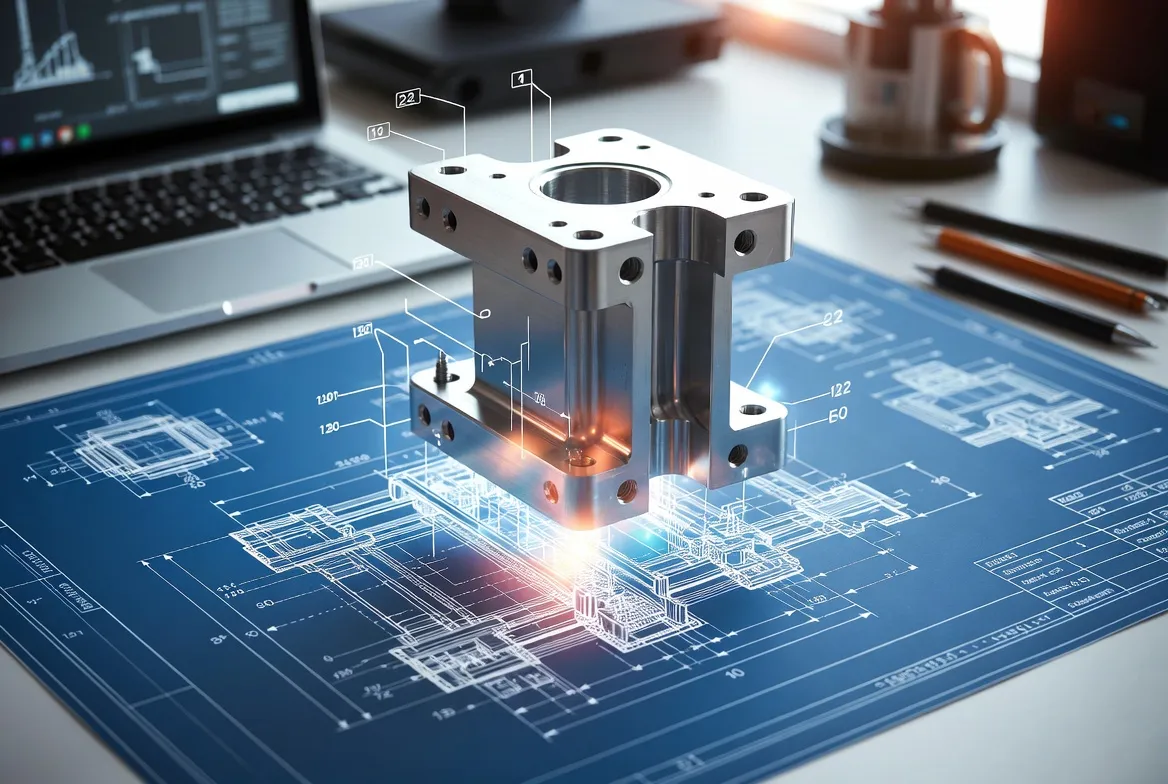
Fabrication shop drawings are detailed technical illustrations that provide comprehensive instructions for manufacturing specific building components. These drawings go far beyond basic architectural plans by including precise measurements, material specifications, connection details, and assembly sequences.
Think of them as the translation layer between design intent and physical reality. While architects create design drawings showing what the finished structure should look like, fabrication shop drawings show exactly how to build each individual component.
The drawings typically include multiple views of each component—front, side, top, and sectional views—along with detailed call-outs for welds, fasteners, finishes, and tolerances. Every measurement matters because fabricators rely on these drawings to cut, form, weld, and assemble components that must fit perfectly during installation.
The Role in Construction Workflow
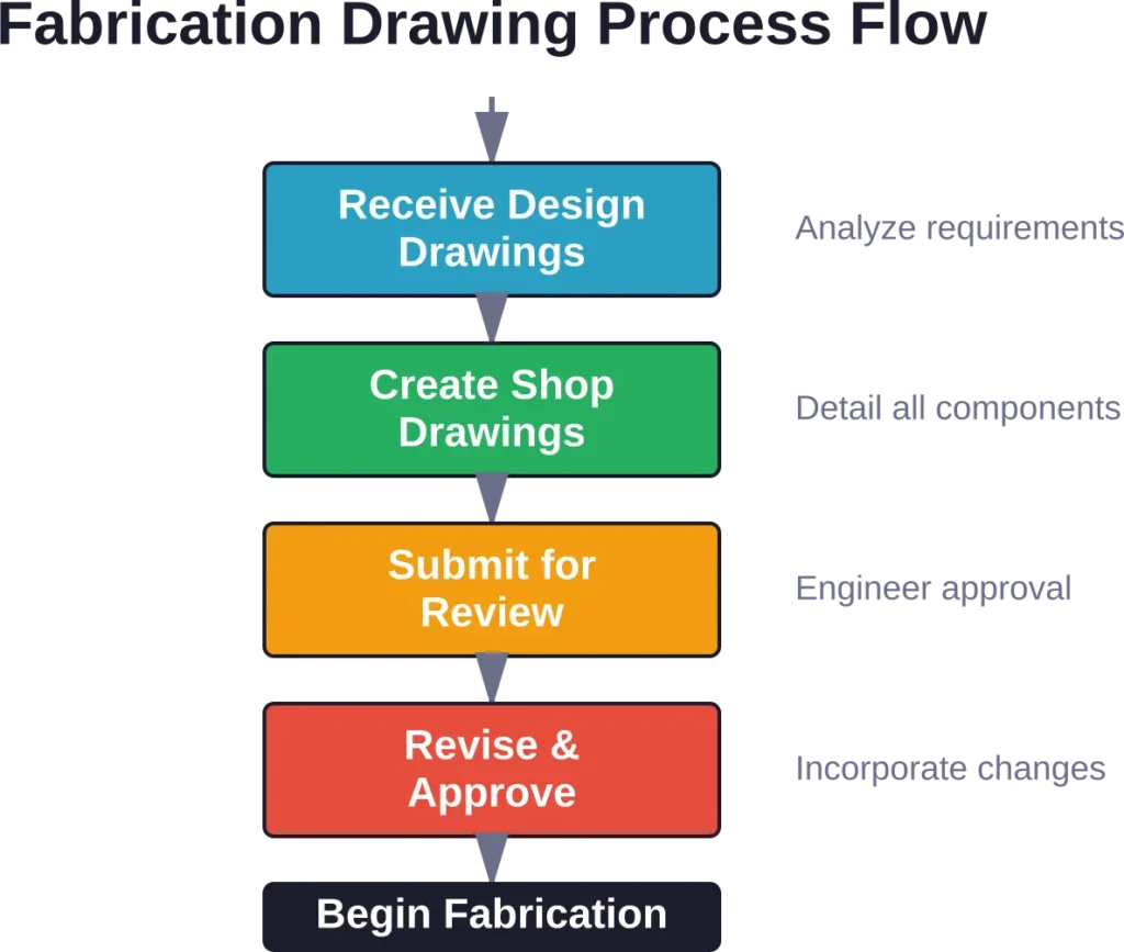
Fabrication shop drawings occupy a specific position in the construction documentation hierarchy. Design professionals create initial architectural and engineering drawings showing the overall structure. These get submitted for permits and approvals.
Once approved, specialized drafters or engineers create fabrication shop drawings based on the design documents. These detailed drawings get reviewed by the original design team, then sent to fabrication shops where workers use them to manufacture actual components.
This workflow ensures accountability at every stage. The design team verifies the fabrication drawings match their intent. The fabrication shop confirms they can build what’s documented. And inspectors can verify finished components against the approved shop drawings.
Types of Fabrication Drawings
Different projects require different drawing types, each serving specific purposes in the fabrication and construction process. Understanding these distinctions helps teams communicate more effectively and avoid costly mistakes.
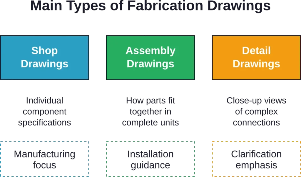
Shop Drawings
Shop drawings focus on individual components and their manufacturing requirements. A steel beam shop drawing, for example, shows exact length, cross-sectional dimensions, hole locations for bolts, weld symbols, material grade, and surface finish requirements.
These drawings get used directly on the fabrication floor. Welders, machinists, and fabricators reference them constantly while working. The level of detail must be sufficient for someone with trade skills but no involvement in the design process to manufacture the component correctly.
Steel shop drawings represent the most common type, particularly in structural construction. They include member marks (unique identifiers), material specifications following industry standards, and connection details showing exactly how pieces join together.
Assembly Drawings
Assembly drawings show how individual fabricated components fit together to form larger systems or structures. Rather than focusing on manufacturing a single piece, these drawings illustrate the relationship between multiple components.
For complex structures, assembly drawings become essential navigation tools. They show the sequence of installation, temporary support requirements, and how components align in three-dimensional space. Installation crews rely heavily on these drawings during construction.
The level of detail differs from shop drawings. Assembly drawings prioritize spatial relationships and installation sequence over manufacturing specifics. They answer questions like “which piece connects to what” and “in what order should installation proceed.”
Detail Drawings
Detail drawings provide enlarged views of complex connections, joints, or features that require additional clarification. When a standard shop drawing can’t clearly show a complicated detail at its normal scale, a separate detail drawing gets created.
These drawings often include sectional views cutting through assemblies to show internal construction. They might show a complex weld joint from multiple angles, or illustrate exactly how a custom bracket attaches to both a beam and a column.
Detail drawings prevent interpretation errors. By providing crystal-clear illustrations of complicated features, they eliminate guesswork and reduce the likelihood of fabrication mistakes that only get discovered during installation.
Prepare Fabrication Shop Drawings for Construction Delivery

Fabrication shop drawings are used to support manufacturing, installation, and construction coordination workflows. Powerkh provides shop drawing support for contractors, fabricators, and project delivery teams.
Need Fabrication Shop Drawing Support?
Talk with Powerkh to:
- prepare fabrication-ready drawings
- support structural and MEP coordination
- improve documentation before production starts
- update drawings during project delivery
Review your fabrication drawing requirements with the Powerkh team.
Key Components of Fabrication Shop Drawings
Effective fabrication shop drawings share common elements that convey information consistently and completely. Understanding these components helps both creators and users of these technical documents.
| Component | Purpose | Critical Details |
|---|---|---|
| Title Block | Identifies the drawing and project | Project name, drawing number, revision, date, company |
| Dimensions | Specifies exact sizes | Overall dimensions, detail dimensions, hole locations |
| Material Specifications | Defines what to use | Material grade, thickness, finish requirements |
| Weld Symbols | Shows joining methods | Weld type, size, length, location per ASME standards |
| Notes and Callouts | Provides additional instructions | Special processes, tolerances, inspection requirements |
| Scale and Views | Establishes drawing interpretation | Scale ratio, orthographic views, sections |
Dimensions and Tolerances
Dimensions represent the most fundamental information on fabrication drawings. But raw dimensions alone aren’t sufficient—tolerances define acceptable variation from nominal measurements.
According to ASME Y14.5 standards, geometric dimensioning and tolerancing (GD&T) provides a universal language for specifying dimensional requirements. These standards guide modern CAD software and establish consistency across industries.
Real talk: tolerances matter more than many designers realize. Materials expand and contract. Cutting tools wear. Welding introduces distortion. Fabrication shop drawings must account for these realities by specifying appropriate tolerances—tight enough to ensure fit and function, loose enough to be manufacturable at reasonable cost.
Material and Finish Specifications
Fabrication drawings must clearly specify materials using industry-standard designations. For steel, this includes ASTM grades. For aluminum, alloy and temper designations. For other materials, appropriate standard specifications.
Surface finish requirements also get documented. Will the component be painted? Hot-dip galvanized? Left as mill finish? These specifications affect both fabrication processes and final appearance.
Material specifications directly impact cost. Specifying an exotic alloy when standard mild steel would suffice unnecessarily inflates expenses. Fabrication drawings should specify the minimum material properties required for the application.
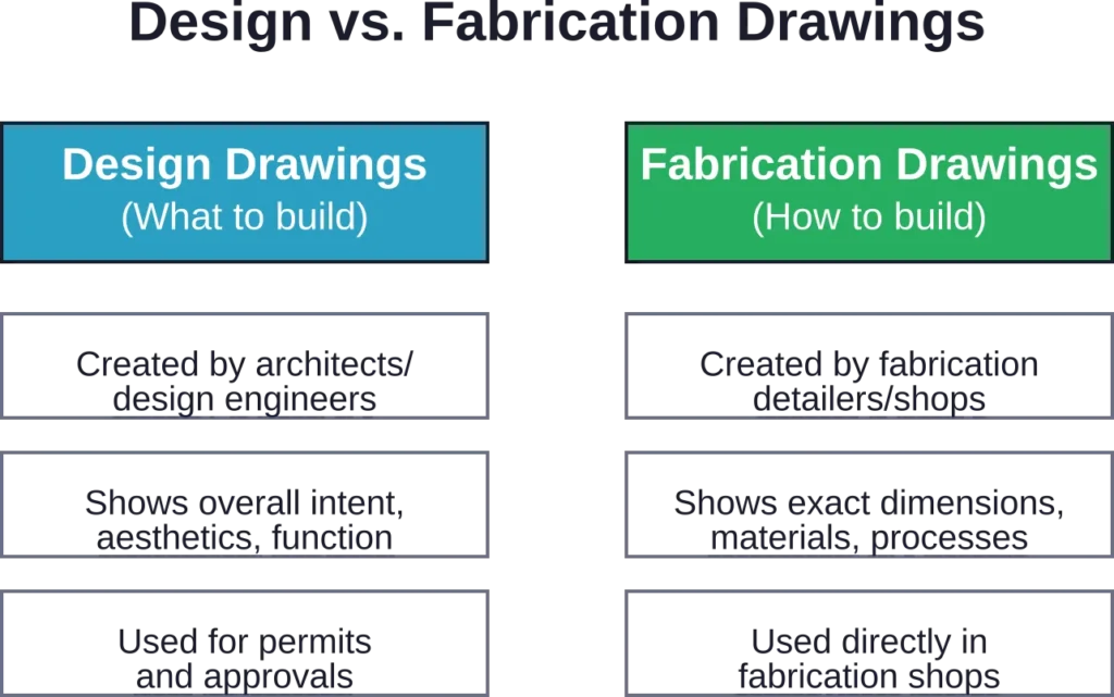
The Difference Between Design Drawings and Fabrication Shop Drawings
Confusion often arises between design drawings and fabrication shop drawings. While related, these serve fundamentally different purposes and audiences.
Design Intent vs. Manufacturing Reality
Design drawings communicate the architect’s or engineer’s vision. They show spatial relationships, aesthetic qualities, performance requirements, and design intent. These drawings get submitted for building permits and serve as the contract documents.
Fabrication shop drawings translate that intent into manufacturable reality. They incorporate the fabricator’s expertise about how to actually build the components. This includes considering material availability, standard sizes, manufacturing processes, and practical construction methods.
Here’s the thing though—design drawings often contain ambiguities or impractical details. The fabrication drawing process resolves these issues before manufacturing begins, preventing costly mistakes and change orders.
Level of Detail
Design drawings typically show buildings or structures at smaller scales—1/4 inch to 1 foot is common for architectural plans. At this scale, showing every bolt hole or weld detail would clutter the drawing beyond usability.
Fabrication shop drawings work at much larger scales, often full size (1:1) or close to it. This allows inclusion of every dimension, hole, notch, and detail required for fabrication. The increased scale makes the drawings practical working documents for shop personnel.
The information density differs dramatically. A single design drawing might show an entire building floor. The fabrication shop drawings for that same floor might comprise hundreds of individual sheets, each showing specific components in complete detail.
Why Fabrication Shop Drawings Matter
The importance of quality fabrication shop drawings extends far beyond mere documentation. These drawings directly impact project success across multiple dimensions.
Error Prevention and Cost Control
Errors discovered during fabrication are expensive. Errors discovered during installation are catastrophically expensive. Quality fabrication shop drawings catch problems before steel gets cut or welded.
The shop drawing review process creates a crucial checkpoint. Design teams review fabrication drawings to verify they match design intent. This review catches dimensional conflicts, missing information, or impractical details before they become physical problems.
When fabrication drawings are incomplete or inaccurate, fabricators must stop work and request clarification. These delays cascade through project schedules. Components arrive late to job sites. Installation crews wait idle. Other trades get delayed. The cost multiplies quickly.
Quality Assurance
Fabrication shop drawings establish the standard against which finished components get inspected. Quality control personnel compare manufactured pieces to approved shop drawings, verifying dimensions, materials, and details match specifications.
This documentation creates accountability. If a component doesn’t fit during installation, the shop drawings provide clear evidence of whether the problem stems from fabrication error, installation error, or design issues.
For structural steel and other critical applications, shop drawings become part of the permanent project record. They document exactly what got built, which matters for future modifications, repairs, or forensic investigations.
Communication Across Disciplines
Construction projects involve numerous parties—architects, engineers, general contractors, specialty contractors, fabricators, and installers. Each group has different expertise and perspectives.
Fabrication shop drawings provide a common language everyone understands. Rather than verbal descriptions or vague sketches, these precise technical documents eliminate ambiguity. A dimension is a dimension. A weld symbol has specific meaning per ASME standards.
This clarity reduces disputes and finger-pointing. When everyone works from the same detailed drawings, responsibilities become clear and coordination improves dramatically.
Creating Effective Fabrication Shop Drawings
Producing quality fabrication shop drawings requires both technical skill and practical manufacturing knowledge. The best drawings combine engineering precision with fabrication expertise.
Tools and Software
Modern fabrication shop drawings are created digitally using CAD (Computer-Aided Design) software. Programs like AutoCAD, Tekla Structures, SDS/2, and Revit dominate the structural steel industry, each offering specialized tools for fabrication detailing.
These programs link to databases of standard steel shapes, connection details, and fasteners. They automatically generate bills of material from the 3D model. Many can produce CNC (Computer Numerical Control) files that directly drive fabrication equipment.
But here’s what matters most: the software is just a tool. Understanding fabrication processes, material behavior, and construction sequencing matters more than CAD proficiency. The best detailers combine software skills with hands-on fabrication experience.
Standards and Conventions
ASME Y14 standards provide the foundational framework for engineering drawings in North America. According to ASME’s Y14 standards documentation, these standards guide the product development process from concept through delivery, establishing the language for production, inspection, and CAD software.
Line conventions, dimensioning practices, weld symbols, and drawing organization all follow established standards. Using these conventions ensures drawings can be understood by fabricators and inspectors regardless of who created them.
Different industries have additional specific standards. Structural steel follows AISC (American Institute of Steel Construction) guidelines. Each specialty—whether mechanical, electrical, or architectural—has conventions practitioners recognize.
Best Practices for Clarity
Clear fabrication shop drawings share certain characteristics. Dimensions are placed logically, following the sequence fabricators need them. Related dimensions get grouped together. Overall dimensions are clearly distinguished from detail dimensions.
Views are arranged systematically. The main orthographic views (front, top, side) occupy predictable positions. Sections and details are placed nearby with clear reference markers showing where they cut through the main views.
Notes and callouts are concise but complete. They specify what needs to be done without excessive verbiage. Generic notes that apply to all drawings go in a standard location. Component-specific notes are placed directly on the relevant view.
Common Challenges and Solutions
Even experienced detailers and fabricators encounter recurring challenges with fabrication shop drawings. Recognizing these issues helps teams implement preventive measures.
| Challenge | Impact | Solution |
|---|---|---|
| Incomplete dimensions | Fabrication delays, errors, rework | Use checklists, peer review, dimension validation tools in CAD |
| Conflicting information | Confusion, disputes, wrong fabrication | Single source of truth, clear revision tracking, coordination meetings |
| Late changes | Schedule delays, cost overruns, rushed work | Change management process, impact assessment, schedule buffers |
| Material substitutions | Performance issues, approval delays | Early material verification, approved equals list, engineer consultation |
| Tolerance stack-up | Components don’t fit during assembly | Tolerance analysis, coordination between trades, field verification |
Dimensional Conflicts
Large projects involve thousands of components designed by different people at different times. Dimensional conflicts—where two components occupy the same space—inevitably occur.
Advanced 3D modeling helps detect conflicts during the design phase. Clash detection software automatically identifies where steel, ductwork, piping, and other systems interfere. But this only works when models are complete and current.
The solution requires coordination. Regular coordination meetings bring all trades together to review 3D models and resolve conflicts before fabrication begins. This proactive approach prevents discovering interference issues during installation when solutions are expensive and limited.
Unclear Tolerances
When fabrication drawings don’t specify tolerances, fabricators must guess what’s acceptable. Different fabricators might interpret requirements differently, leading to inconsistent results.
Standard tolerances help. Many projects specify that unless otherwise noted, dimensions follow standard fabrication tolerances published by industry organizations like AISC. These defaults provide baseline expectations.
But critical dimensions need explicit tolerances. Connection points between components, anchor bolt locations, and features requiring precise alignment should have clearly specified acceptable variation. This prevents arguments about whether dimensions are acceptable.
Revision Control
Fabrication drawings rarely remain static. Design changes occur. Field conditions differ from assumptions. Problems get discovered requiring modifications.
Poor revision control creates chaos. Fabricators working from outdated drawings manufacture wrong components. Installers arrive with superseded installation drawings. Inspectors compare work to obsolete specifications.
Rigorous revision management prevents these problems. Each drawing sheet has a revision number and date. Revision clouds highlight changed areas. Distribution logs track who received which revision. These practices ensure everyone works from current information.
Industry Applications of Fabrication Shop Drawings
While steel construction represents the most common application, fabrication shop drawings are essential across numerous industries and project types.
Structural Steel Construction
Steel-framed buildings depend absolutely on accurate shop drawings. Every beam, column, connection plate, and fastener appears in detailed fabrication drawings before any cutting or welding occurs.
The complexity can be staggering. A medium-size commercial building might require 300-500 shop drawing sheets covering thousands of individual steel components. Each piece needs unique identification, exact dimensions, and complete connection details.
Steel fabrication shops employ specialized detailers who create these drawings using industry-specific software. Their expertise combines structural engineering knowledge with practical fabrication experience, ensuring drawings are both technically correct and buildable.
Mechanical and HVAC Systems
Complex mechanical systems require detailed fabrication drawings for ductwork, piping, equipment supports, and specialty components. These drawings coordinate mechanical systems with structural elements and architectural features.
HVAC fabrication drawings show duct sizes, fittings, transitions, dampers, and support locations. They account for space constraints, access requirements, and coordination with other building systems. Fabrication shops use these drawings to cut and assemble ductwork before delivery to the job site.
Architectural Metals and Specialty Items
Custom railings, ornamental metalwork, curtain wall systems, and architectural features all require fabrication drawings. These blend aesthetic considerations with structural requirements and manufacturing constraints.
Architectural metal fabrication often demands tighter tolerances than structural steel. Visible components require precision fit and finish. The fabrication drawings must specify not just dimensions but also surface preparation, finish requirements, and assembly sequences that prevent damage to finished surfaces.
The Future of Fabrication Shop Drawings
Technology continues transforming how fabrication shop drawings are created, distributed, and used. Several trends are reshaping the industry.
Building Information Modeling Integration
BIM (Building Information Modeling) creates comprehensive 3D digital models containing geometric and functional information about building components. Rather than separate 2D drawings, BIM produces integrated models used throughout design, fabrication, and construction.
Fabrication information increasingly gets embedded directly in BIM models. According to NIST research published June 9, 2022, updated ASME Y14.46 standard provides fundamental guidance for 3D-printing design rules and documentation, showing how additive manufacturing integrates with digital design processes.
Model-based definition (MBD) eliminates traditional 2D drawings entirely. All manufacturing information—dimensions, tolerances, materials, processes—attaches directly to 3D model geometry. Fabricators work from intelligent 3D models rather than printed sheets.
Automated Detailing and AI Assistance
Software increasingly automates repetitive aspects of fabrication detailing. Connection design tools automatically generate standard connections based on member sizes and loads. Detailing software automatically numbers components, generates bills of material, and produces standard views.
Artificial intelligence assists with tasks like clash detection, optimization, and error checking. Machine learning algorithms trained on thousands of projects can identify common mistakes and suggest corrections before drawings get submitted for review.
That said, human expertise remains essential. Automated tools assist but don’t replace the judgment and experience skilled detailers bring. Unusual conditions, complex geometry, and project-specific requirements still demand human problem-solving.
Direct Digital Manufacturing
CNC cutting equipment, robotic welding, and automated fabrication systems read digital files directly from fabrication models. The shop drawings effectively become machine instructions rather than documents for human fabricators.
This direct digital workflow eliminates transcription errors. Dimensions don’t get misread. Hole locations are precisely where the model specifies. Automated equipment manufactures components with consistency impossible for manual fabrication.
The fabrication drawing transforms from a communication document into manufacturing data. But the underlying principles remain—complete information, proper tolerances, clear specifications, and thorough review before fabrication begins.
Frequently Asked Questions
Working drawings is a broader term encompassing all construction documents including architectural, structural, mechanical, and electrical drawings. Shop drawings are a specific subset created by fabricators showing detailed manufacturing information for particular components. Working drawings show what to build overall; shop drawings show exactly how to fabricate specific pieces.
Fabrication shops or specialized detailing firms typically create shop drawings, not the original design team. The fabricator brings manufacturing expertise to translate design intent into buildable reality. However, the design engineer or architect reviews and approves shop drawings to verify they match design requirements before fabrication proceeds.
Timeline varies dramatically based on project complexity. Simple projects might complete shop drawings in 2-3 weeks. Complex structures can require 2-3 months for initial drawing creation plus additional time for review cycles and revisions. Fast-track projects sometimes compress schedules, but rushing shop drawings increases error risk significantly.
Requirements depend on project type and complexity. Simple projects using standard components might not need detailed shop drawings. But projects involving custom fabrication, structural steel, complex mechanical systems, or specialty items almost always require shop drawings. Contract documents specify shop drawing requirements for each project.
Errors discovered during review get marked up and returned to the fabricator for correction before approval. Errors not caught until fabrication produce wrong components requiring rework or replacement at the fabricator’s expense. Errors discovered during installation cause expensive delays and may require field modifications or emergency re-fabrication.
Standard connection details or typical components might be reused, but complete shop drawing sets are project-specific. Every building has unique dimensions, loads, site conditions, and design requirements. Attempting to reuse shop drawings from previous projects without complete verification creates serious risk of errors and component mismatch.
Digital 3D models increasingly supplement or replace 2D shop drawings, particularly in fabrication shops with CNC equipment. But many projects still produce traditional 2D drawing sheets alongside 3D models. The transition to fully model-based workflows continues, but 2D fabrication drawings remain standard practice in many sectors and regions.
Conclusion: The Foundation of Successful Fabrication
Fabrication shop drawings represent far more than technical documentation—they’re the essential translation layer between design vision and physical reality. These detailed drawings ensure components get manufactured correctly, fit together properly, and meet project requirements.
Quality fabrication shop drawings prevent costly errors, enable efficient manufacturing, facilitate installation, and create permanent project records. They establish clear communication across all project participants and provide accountability throughout the construction process.
The investment in thorough, accurate fabrication shop drawings pays dividends through reduced rework, fewer field problems, improved quality, and better project outcomes. Whether for structural steel, mechanical systems, or architectural components, these drawings form the foundation of successful fabrication.
For teams planning construction or manufacturing projects, prioritizing the fabrication shop drawing process—allocating sufficient time, engaging qualified detailers, conducting thorough reviews—directly contributes to project success. The details matter, and fabrication shop drawings are where those details get documented with precision.