
Quick Summary: Steel shop drawings are detailed technical documents created during the fabrication phase that show exact measurements, materials, connections, and assembly instructions for every steel component in a construction project. They translate architectural and engineering designs into fabrication-ready instructions that steel fabricators and erectors use to manufacture and install structural steel members. These drawings include connection details, bolt patterns, weld specifications, material grades, and piece marks that ensure accurate production and site assembly.
Walk into any construction site where steel frames reach toward the sky, and somewhere behind that impressive structure sits a stack of incredibly detailed technical drawings. These aren’t the architectural plans that show what the building will look like when finished. They’re steel shop drawings—the practical, nuts-and-bolts documents that tell fabricators exactly how to cut, drill, weld, and assemble every single piece of steel.
Without these drawings, structural steel fabrication would be guesswork. With them, precision becomes possible.
Defining Steel Shop Drawings
Steel shop drawings are specialized fabrication documents that provide comprehensive instructions for manufacturing and assembling structural steel components. They take the broad design intent from architectural and engineering plans and transform it into actionable, dimension-specific guidance that fabrication shops can follow.
These drawings show every connection, every bolt hole, every weld location, and every measurement needed to produce steel members that fit together perfectly on site. They include details that engineering drawings typically don’t cover—like exact bolt patterns, connection plate thicknesses, weld sizes, material grades for each piece, and assembly sequences.
The term “shop drawing” specifically refers to the fabrication phase. These documents get created after design approval but before actual steel cutting begins. They serve as the bridge between what engineers envision and what fabricators produce.
Key Components Found in Steel Shop Drawings
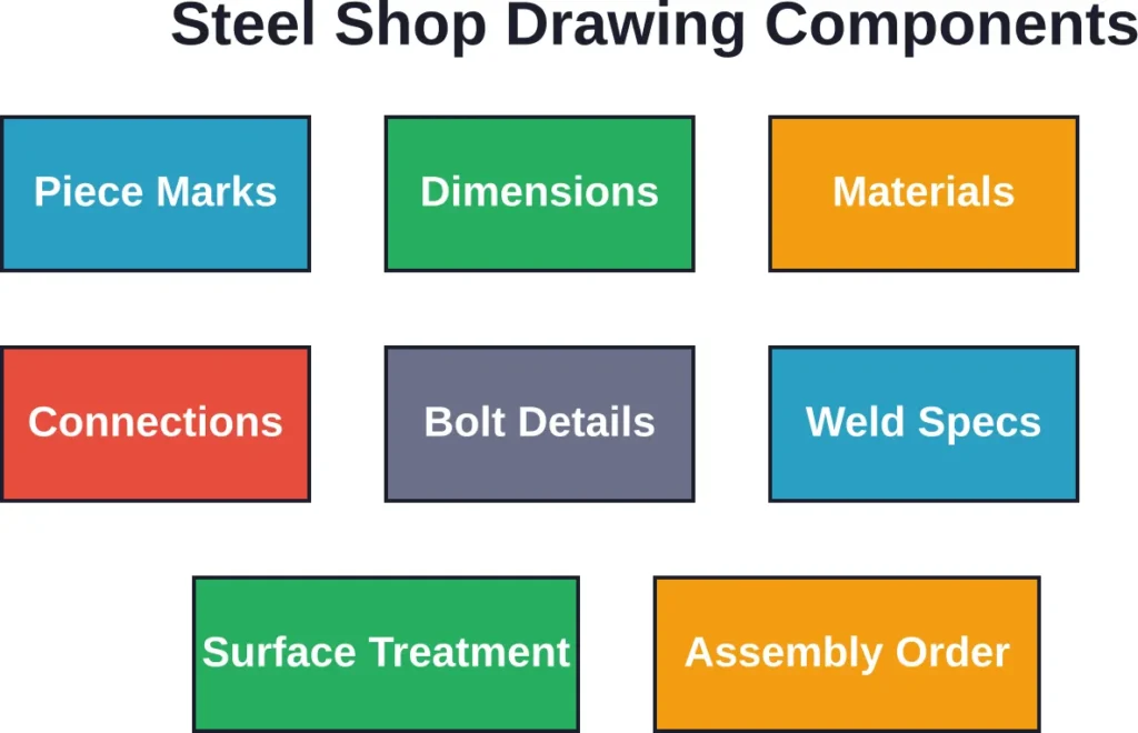
Every steel shop drawing contains specific information that fabricators rely on:
- Piece marks and identification numbers for tracking individual components through fabrication and erection
- Exact dimensions including lengths, widths, depths, and angles for every steel member
- Material specifications noting steel grades, thicknesses, and types (W-beams, channels, angles, plates)
- Connection details showing how members attach to each other with bolts or welds
- Bolt information including quantities, sizes, grades, and precise hole locations
- Weld specifications with symbols indicating weld types, sizes, and locations per industry standards
- Surface treatment notes for coatings, finishes, or fireproofing requirements
- Assembly sequences showing the order in which components fit together
ASME Y14 standards establish symbols, rules, definitions, requirements, and recommended practices for engineering drawings, including those used in steel detailing. These standards cover everything from line conventions to digital product definition methods used in modern CAD systems.
How Steel Shop Drawings Differ from Other Construction Documents
Construction projects involve several types of drawings, and understanding the differences prevents confusion. Architectural drawings show the overall building design—what it looks like, spatial relationships, finishes, and general layout. Engineering drawings provide structural calculations and load-bearing requirements with design intent.
Steel shop drawings take that engineering intent and add the practical manufacturing details. They’re more specific than engineering drawings but focused solely on fabrication and assembly. An engineering drawing might show a beam-to-column connection conceptually; the shop drawing shows that same connection with every bolt hole coordinate, plate dimension, and weld size specified.
Then there are erection drawings—another subset that shows field crews how to assemble pre-fabricated steel members on site. Erection drawings focus on piece identification, lifting points, assembly sequences, and field connections. Shop drawings focus on what happens in the fabrication facility before steel ever reaches the construction site.
| Drawing Type | Primary Purpose | Level of Detail | Primary User |
|---|---|---|---|
| Architectural | Overall building design and aesthetics | Conceptual and spatial | Owners, designers, contractors |
| Engineering | Structural design and load requirements | Calculation-based with design intent | Engineers, contractors |
| Shop Drawings | Fabrication instructions | Highly specific dimensions and methods | Steel fabricators, detailers |
| Erection Drawings | On-site assembly guidance | Assembly sequences and connections | Erection crews, field supervisors |
The Steel Shop Drawing Creation Process
Creating these drawings requires specialized knowledge and software. Steel detailers—professionals trained in both engineering principles and fabrication methods—develop shop drawings using advanced CAD systems and 3D modeling tools.
The process typically follows this sequence:
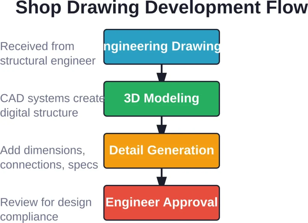
First, detailers receive approved engineering drawings from the structural engineer of record. They review these documents alongside architectural plans to understand the complete project scope and any potential conflicts between disciplines.
Next comes the modeling phase. Detailers create 3D models of the steel structure using specialized software that understands steel connections, standard sections, and fabrication constraints. This digital model becomes the foundation for all subsequent shop drawings.
From the 3D model, detailers generate individual part drawings showing each unique steel component. They add dimensions, material callouts, hole locations, and fabrication notes. Connection details get developed showing exactly how members join together.
But here’s where it gets interesting—detailers must account for real-world fabrication limitations. Steel mills don’t produce infinite length beams. Welding positions affect joint design. Bolt access requires clearance. Transportation limits dictate maximum piece sizes. All these practical constraints get incorporated into shop drawings.
After internal review and quality checks, shop drawings go to the structural engineer for approval. Engineers verify that the detailed connections and member sizes match design intent and can carry required loads. This review process often involves several rounds of revisions.
Technology’s Role in Modern Shop Drawing Production
Steel detailing has transformed dramatically over recent decades. Drafting practices have evolved to incorporate 2D CAD and 3D modeling with increasingly automated drawing generation. Modern detailing software creates shop drawings directly from 3D models, ensuring consistency and reducing errors.
These systems integrate with fabrication equipment, allowing CNC machines to read shop drawing data and automatically cut, drill, and punch steel components. The digital workflow from design through fabrication improves accuracy and speeds up production timelines.
Prepare Steel Shop Drawings for Fabrication and Site Delivery
Steel shop drawings are used to support fabrication, coordination, and installation workflows for structural steel projects. Powerkh provides steel detailing, BIM coordination, and fabrication drawing support for construction teams and fabricators.
Need Steel Shop Drawing Support?
Talk with Powerkh to:
- prepare fabrication-ready steel drawings
- support structural BIM coordination workflows
- improve detailing before production starts
- coordinate steel models with project teams
Talk with Powerkh about steel detailing and fabrication support.
Why Precision Matters in Steel Shop Drawings
Structural steel projects demand accuracy measured in fractions of inches. A beam that’s too short won’t span its supports. Bolt holes that don’t align create costly field modifications. Incorrect connection details compromise structural integrity.
Steel shop drawings provide that precision. They eliminate ambiguity by documenting every dimension explicitly. Fabricators don’t need to interpret or assume—the drawings tell them exactly what to produce.
This precision translates directly into project efficiency. Accurate shop drawings mean steel components arrive on site ready to assemble without modifications. Field crews can follow erection sequences without delays. The building schedule stays on track because the fabrication phase went smoothly.
The cost implications are significant too. Rework and field corrections drain project budgets rapidly. A single incorrectly fabricated beam might require shipping back to the shop, re-cutting, re-drilling, and re-delivery—expenses that multiply when schedule delays push other trades behind. Quality shop drawings prevent these problems before they start.
Coordination Across Construction Disciplines
Steel doesn’t exist in isolation within buildings. It interfaces with concrete foundations, mechanical systems, electrical conduits, and architectural finishes. Shop drawings help coordinate these intersections.
Detailers identify conflicts during the shop drawing phase—places where steel beams might interfere with ductwork, or where embed plates need specific locations in concrete pours. Resolving these clashes on paper costs far less than discovering them on site when concrete has already hardened or steel has been erected.
Different Types of Steel Shop Drawings
Not all steel shop drawings serve the same function. Different drawing types focus on specific aspects of fabrication and construction:
General arrangement drawings provide overview layouts showing how major steel components relate spatially. They give fabricators and erectors the big picture before diving into details.
Assembly drawings show how individual parts fit together into larger subassemblies. A built-up column might consist of plates, stiffeners, and connection elements—the assembly drawing shows how these pieces join.
Part drawings detail individual steel members with all dimensions, holes, cuts, and material specifications needed for fabrication. Each unique piece gets its own part drawing.
Erection drawings focus on field assembly, showing piece marks, connections between shipped assemblies, and installation sequences. These guide the crane operators and ironworkers during construction.
Connection details zoom into specific joints, showing bolt patterns, weld specifications, plate arrangements, and assembly procedures for critical connections.
Large structural steel projects might generate hundreds or thousands of individual shop drawings across these categories, all coordinated to ensure the complete structure fits together perfectly.
Common Challenges in Steel Shop Drawing Development
Even experienced detailers face recurring challenges when producing shop drawings. Understanding these helps project teams anticipate and address potential issues:
Incomplete or ambiguous engineering drawings create uncertainty. When design intent isn’t clear, detailers must seek clarification—a process that can delay shop drawing completion. Structural engineers working closely with detailers from project start reduce these communication gaps.
Design changes during the shop drawing phase force revisions that ripple through interconnected components. A revised beam size might require new connection plates, different bolts, and adjusted interfacing members. Managing these change cascades requires careful coordination.
Tight project schedules compress shop drawing development timelines. Rushing the detailing process increases error risk, potentially causing expensive fabrication mistakes. Realistic scheduling that allows adequate detailing time pays dividends in quality.
Coordination with other trades demands attention. Mechanical, electrical, and plumbing systems often need to penetrate or attach to steel members. Accommodating these requirements in shop drawings prevents conflicts during construction.
| Challenge | Impact | Mitigation Strategy |
|---|---|---|
| Unclear engineering drawings | Delays and assumptions | Early coordination meetings with structural engineers |
| Design changes mid-process | Cascading revisions | Change management protocols and version control |
| Compressed schedules | Increased error risk | Realistic timeline planning with adequate buffer |
| Multi-trade coordination | Field conflicts | 3D clash detection and coordination reviews |
Who Uses Steel Shop Drawings and When
Multiple project stakeholders rely on shop drawings at different construction phases:
Fabricators use shop drawings as manufacturing instructions. The shop floor translates dimensions and specifications into cut steel, drilled holes, and welded assemblies. Quality control inspectors verify fabricated pieces against shop drawing requirements.
Structural engineers review shop drawings to confirm fabrication details align with design intent and structural requirements. Their approval stamps indicate the drawings meet engineering standards.
General contractors coordinate shop drawings across trades, managing the approval workflow and ensuring steel fabrication schedules align with overall construction timelines.
Erection contractors reference shop drawings and companion erection drawings during field assembly. Piece marks on drawings correspond to tags on shipped steel, helping crews identify and position each member correctly.
Project inspectors use approved shop drawings as the reference standard when verifying installed steel meets project specifications.
Industry Standards and Best Practices
Professional organizations establish standards that govern shop drawing content and format. ASME’s Y14 standards establish symbols, rules, definitions, requirements, and recommended practices for engineering drawings, including those used in steel detailing. These standards cover everything from line conventions to digital product definition methods.
The American Institute of Steel Construction publishes specifications and codes that influence connection details and fabrication practices reflected in shop drawings. Understanding these standards ensures shop drawings meet industry expectations.
Best practices include clear title blocks with project information, consistent dimensioning methods, standardized symbols and abbreviations, and organized sheet layouts that make information easy to locate. Revision tracking shows drawing history and ensures everyone works from current versions.
Digital standards are evolving too. Building Information Modeling increasingly integrates with steel detailing workflows, enabling 3D coordination and automated clash detection before fabrication begins.
Outsourcing Steel Shop Drawing Services
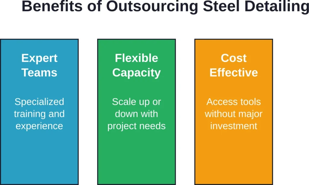
Many construction companies outsource shop drawing production to specialized detailing firms. This approach offers several advantages:
Specialized detailing companies maintain teams trained specifically in steel detailing software and fabrication practices. Their focused expertise often produces higher quality drawings faster than general contractors could internally.
Scalability becomes easier when working with detailing services. Project workloads fluctuate, but maintaining full-time detailing staff for peak demands leaves resources idle during slower periods. Outsourcing provides flexible capacity.
Advanced software and training represent significant investments. Detailing firms spread these costs across multiple clients, making sophisticated tools economically accessible to smaller contractors.
That said, effective outsourcing requires clear communication about project requirements, timely feedback on submitted drawings, and established quality standards. Successful relationships between contractors and detailing services develop through repeated collaboration.
Frequently Asked Questions
Errors caught during engineering review get corrected before fabrication starts. Mistakes discovered during fabrication might require re-work or material replacement, adding cost and schedule delays. Field-discovered errors are most expensive, potentially requiring structural modifications, re-fabrication, and construction delays. This cost progression emphasizes the importance of thorough shop drawing quality control.
Moving Forward with Steel Shop Drawings
Steel shop drawings represent the critical link between structural design and physical construction. They transform engineering concepts into fabrication reality through precise documentation of every dimension, connection, and component specification.
Understanding what these drawings contain, how they’re created, and why they matter helps everyone involved in construction projects—from engineers and fabricators to contractors and inspectors—communicate more effectively and build more successfully.
The investment in quality shop drawings pays returns throughout the project lifecycle. Accurate documentation reduces fabrication errors, eliminates field conflicts, keeps schedules on track, and ultimately delivers safer structures that meet design intent.
Whether developing shop drawings internally or working with specialized detailing services, prioritizing accuracy and clear communication during this phase sets the foundation for construction success. The structural steel that shapes skylines and supports infrastructure begins its journey as detailed lines on carefully prepared shop drawings.